project: NEO
Tutorial on building PS2/PSX Mod-Chips
date: 20.02.2002, written by: wiRe
I've started writing this tutorial cause i bought my first ps2 a few days ago and had to decide which boot method for my development discs i should choose. One very simple method presented by Duke (see his homepage),
is simply done by cutting off the connection between board and ps2-laser and place a three-way-switch instead of original controll. On v5 boards this could be done by soldering to the lower 2 pins of the bottem, left connector.
But this method also requests to have some wires come out of my lovely ps2. So what to do? Buy the Messiah, Origa, NEO V4, or what the heck is out there? No prob, if u have too much $'s. Or you could simply buy a NEO 2.2 usb
(external USB-Chip) or a ready-to-solder NEO-Chip... No! Thats too easy. Why don't just get one of this 12C508 PICs they use (at least for the last two chip types), write some bytes to it and put them into your ps2!? I hear
you say: "The Programmers are very expensive!" Ever done a search for this? I have, and i will show you the best method building up a programmer device, what hardware is needed, where to find the software and how to programm
NEO v2.2 on chip. And i think with version 2.2 and the good old AR2 swap method we have a very comfortable way to boot our self-created proggys. At least comfortable enough for me. But more comfort later, means a little bit
of work now...
| Building your own PIC Programmer | next |
I have choosen a very cheap one called "JDM-Programmer".
Take a look at this simple schematics taken from JDM's homepage (see link section).
You will only need to buy 15 components for only 1$...
| peaces | name | description |
| 1x | - | stripboard (13x13 holes) or any other board-type of your choice |
| 1x | COM | 9pin female dsub connector |
| 1x | U1 | 18pin DIL socket |
| 1x | D2 | Z-Diode 5.1V |
| 1x | D6 | Z-Diode 8.2V |
| 4x | D3,D4,D5,D7 | Diode 1N4148 |
| 2x | Q1,Q2 | Transistor BC547B |
| 1x | R1 | Resistor 10k |
| 1x | R2 | Resistor 1.5k |
| 1x | C2 | Capacitor 100uF/25V |
| 1x | C3 | Capacitor 22uF/16V |
Very cheap to buy and easy to build. Dont forget to buy some 12C508 or 12C508A PICs too, or u have to go the same way twice.
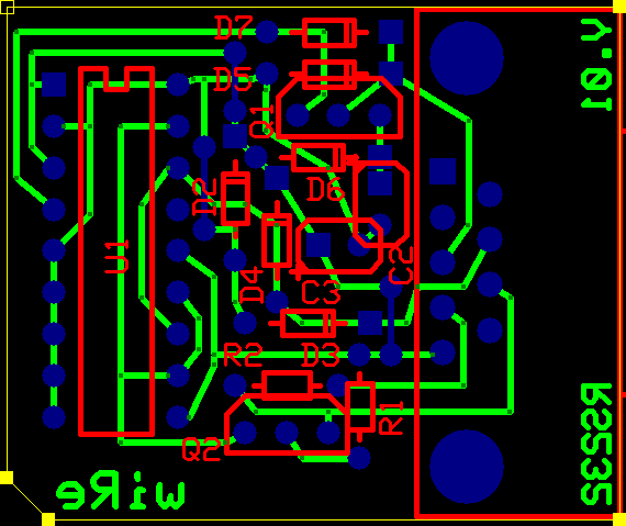
Click here for a stripboard layout by Paul Scrivens. If you want own a good looking programmer (like me), use my pcb layout:

Note: The two transistors in the image above should be flipped horizontal.
Just print this image for the copper layer.
The dimension of the final board is 40x30mm but iam sure u could get it even a bit smaller.
Time to warm up your solder-iron.
| Fuck up your first PIC | next |
There are two good programms out there u need. One is the original software by JDM, running in DOS (have some boot disks lying around?). And you should download the win32 solution, called IC-Prog.
Both could be found inside the download section. Due to the difficulty of timing the pic write commands, its possible to waste some chips before you have the right configuration. The default on IC-Prog is using direct io with
a delay of 4 and all other boxes unchecked. I use IC-Prog to write the data, and JDM's PP2 reading out the PIC's. This is the best combination of both tools.
NOTE: Its possible to write a chip with IC-Prog and get a bad verify, but if u read it with PP2, u see the chip is ok. So, dont panic if this happens.
Also get the Hex-Files of the Mod-chips. I done a lttl fix for the v5 board. When i used the original neo2.2 chip, it only seemed to work after the second reset, so i removed the bad code of this.
Hex file and source code are available. To compile 12C508 assembler get MPLAB, free available from Microchips page. If u use my chip, pay attention to the different usage:
Press the PowerOn/Reset-Button short (below 0.6 seconds) to switch off chip-funtions (mode1). Turn on the PS2 by pressing Eject enables operation mode 2. This means each time you insert
any cd the chip sends SCEx-messages for some time. Holding the button longer than 1 second on power-on turns the chip into mode 3. In this operation mode we are continously sending
SCEx-messages 'till the button is released. To install the chip there are 6 wires needed on pins 1,2,4,5,6 and 8. Direct them to the same places NEO22 would need them. I placed a 1µF cap at
pin 2, negative side pointing to motherboard. Other pins can point to any places. (eg. if u have all wires already setup for neo22, just let them be there, only replace the pic)
If u do a new installation and dont want to solder pins 5 and 6, just wire them to pin 8 on the pic. Doing this enables operation mode 2. Good luck!

top

